Example board · Engineering
Beams: shear, bending and deflection
A revision board made in MySummaries for structural mechanics, shown as the app shows it in study mode. Updated 1 October 2026.
Highlights: the idea a number to know what to do, or the formula a trap
BeamsBeams: shear, bending and deflection11 sections · 3 columns
The six standard cases
| Beam and load | Max shear | Max moment | Where | Max deflection | Worked M: L = 6 m, P = 20 kN, w = 10 kN/m |
|---|---|---|---|---|---|
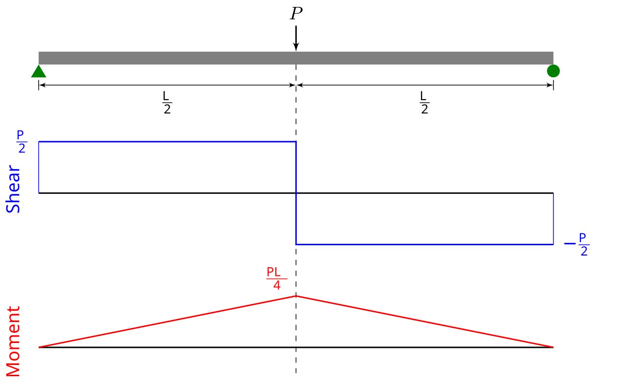
| Simply supported, point load P at midspan | P/2 | PL/4 | Midspan | PL³/48EI | 30 kNm |
| Simply supported, UDL w | wL/2 | wL²/8 | Midspan | 5wL⁴/384EI | 45 kNm |
| Cantilever, point load P at the tip | P | PL | At the support | PL³/3EI, at the tip | 120 kNm |
| Cantilever, UDL w | wL | wL²/2 | At the support | wL⁴/8EI, at the tip | 180 kNm |
| Fixed both ends, point load P at midspan | P/2 | PL/8 | Ends and midspan | PL³/192EI | 15 kNm |
| Fixed both ends, UDL w | wL/2 | wL²/12, hogging | Ends (wL²/24 at midspan) | wL⁴/384EI | 30 kNm (15 at midspan) |
Point load at midspan

Shear stress
- τ = VQ/Ib: Q is the first moment of area beyond the cut
- Largest at the neutral axis, zero at the top and bottom
- Rectangle: = 1.5 V/A
- In an I-beam the web carries almost all of it
Units and traps
- kNm to Nmm is × 10⁶; kN/m is the same as N/mm
- Cantilever: the peak moment is at the support, not the tip
- Fixed ends hog: the moment over the supports is negative
- Don't forget the beam's own weight: it is a UDL
- Many Australian courses plot M on the tension side; the diagram here plots sagging above
The rules that draw the diagrams
- Slope of the shear diagram = the load; slope of the moment diagram = the shear
- So M peaks where V crosses zero
- No load: V flat, M straight. UDL: V sloped, M a parabola
- Point load: a step in V, a kink in M. Applied couple: a step in M
- The change in M between two points = the area under V between them
Bending stress
- σ = My/I; at the extreme fibre σ = M/Z, with
- Zero on the neutral axis, largest at the top and bottom
- Sagging: compression on top, tension underneath
- Rectangle b × d: I = bd³/12, Z = bd²/6
Deflection
- EI d²y/dx² = M: integrate twice, then fit the supports
- Point load: δ ∝ L³. UDL: δ ∝ L⁴, so double the span, 16× the sag
- Superposition: add the cases, since the beam stays linear elastic
- Serviceability: span/250 is a common total-deflection limit (AS 3600)
Drawing them, in order
- Free-body diagram; the reactions from ΣFy = 0 and ΣM = 0
- Cut at each change of load; take equilibrium of one side
- Plot V left to right: steps at point loads, slopes under UDLs
- Plot M from the areas under V
- Check M returns to zero at a pinned or free end
Supports and reactions
- Pin: two reactions, no moment. Roller: one reaction
- Fixed: two reactions and a moment
- Simply supported and cantilever: statically determinate
- Fixed–fixed or propped: indeterminate, so add compatibility (deflection) to equilibrium
Why beams are deep
- I grows with d³: double the depth for 8× the stiffness
- Z grows with d²: double the depth for 4× the strength
- Double the width: only 2× of each
- An I-section puts its area in the flanges, where the stress is
Worked: 6 m span, 10 kN/m
- Reactions wL/2 = 30 kN; = wL²/8 = 45 kNm
- 200 × 400 mm: Z = 5.33 × 10⁶ mm³, σ = M/Z = 8.4 MPa
- E = 10,000 MPa, I = 1.07 × 10⁹ mm⁴: δ = 15.8 mm
- Span/250 = 24 mm: it passes
More for the FE Exam: guides and practice questions.
Make your own board. Build a board of your own from your notes, and MySummaries writes the flashcards, practice papers and audio lectures from it. Free plan: 20 cards, a paper, a lecture and a viva to try.
Make your own board